Tool axis control: Multiblade
Introduction
This topic will explain the options found in the Tool axis control tab of the Multiblade operation.
Tool axis control
The Tool axis control tab allows you to set the tilt of the tool, angle limits, and clearance types and values.
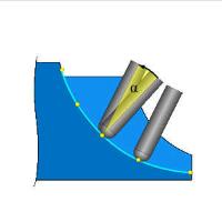
Tilting
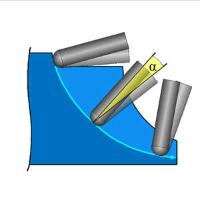
Tilting will allow the user to define a tilting range for the lead angle. The system finds the best solution within this range to machine most of the area and provide optimal tilting. The user specifies four angles:
-
Preferred lead angle - specifies the angle which should be applied when possible.
-
Min. lead angle - specifies the smallest allowable lead angle.

-
Max. lead angle - specifies the largest allowable lead angle.
-
Side tilt angle - specifies the angle of side tilt to be used.
Note: The system tries to stick to the preferred lead angle whenever possible. If not possible the lead angle deviates between the min. and max. angles.
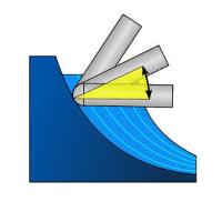
Limits
- Machine angle limits
The machine angle limits makes it possible to define only those cuts which are defined in a conical limit, along rotational axis. The tool axis direction is forced between the min and max machine angle limits. In case the tool cannot reach areas in the toolpaths in order to respect the limits then the portion of the toolpath will be trimmed. - With this check box selected, machine angle limits are defined and enforced.
 - With this check box cleared, machine angle limits are not taken into account.
 - Min. machine angle limit - With the Machine angle limits check box selected, this value defines the minimum allowable machine angle value.
- Max. machine angle limit - With the Machine angle limits check box selected, this value defines the maximum allowable machine angle value.

- Maximum angle step - defines the largest allowable angle change between two toolpath segments.
- Maximum angle step for rapid moves - defines the largest allowable angle change between two toolpath segments of clearance area travel.
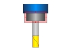
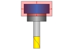
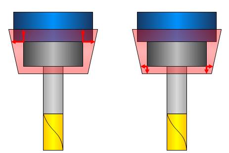
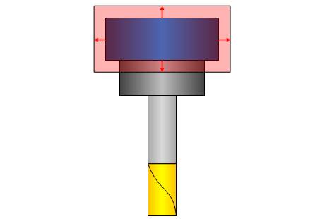
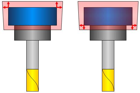
Clearance type
-
 Cylindrical - applies a cylindrical offset to the holder, arbor and shaft.
-
 Conical - applies a conical offset to the holder, arbor and shaft.
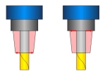


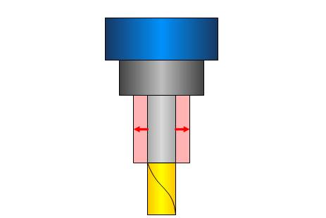
Clearance values
The available Clearance values define the clearance for the Shaft, Arbor, and Holder. While there is a single value available when the Cylindrical Clearance type is used, there are two values, defining the top and bottom, when a Conical Clearance value is used.
|
|
|
|
|---|---|---|
|
|

|
|

|
|
|
|
|
Important: These values should be greater than the allowance being left on the surfaces.
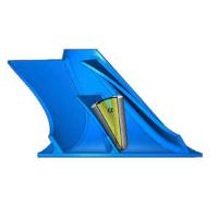
Angular clearance
The Angular clearance creates a conical clearance area around the tool. The angles origin varies based on the type of tool selected. In the case of a flat end mill, the angle will originate from the bottom diameter of the tool. In the case of an end mill with a radius, the angle will originate from the tangency of the radius.
| End Mill | Ball End Mill |
|---|---|
Note:
When Angular clearance is used in conjunction with the regular clearance values, clearance values will extend the area of angular clearance.
![]()
![]()